
Homepage of Stefan Salewski
USB -- Universal Serial Bus
On this page an experimentation board is presented, which makes it possible to connect the AVR-microcontroller AT90USB (1287) to a PC using the USB. The main purpose of this board was the development of free, open-source (GPL) USB-firmware for this controller and testing this firmware in connection with a GNU/Linux-PC. However the board can be used for various experiments and tasks in the area of measurement, control and regulation.
(I have to admit that the schematic is not really nice and clear. This was my first project done with the free gEDA software, so I was not too much concerned with details. The PCB has wide traces, this was intended to make it possible to build the board at home.)
Further informations concerning this controller and a detailed description of the USB firmware (USB-Device-Stack) can be found here:
Experimentation board for the AT90USB (1287)
The AT90USB belongs to the family of AVR-microcontrollers and supports the USB-speeds Low- and Full-Speed, but not High-Speed. The 8-Bit-Controller can operate at frequencies up to 16 MHz and needs only one clock cycle for most of its instructions. It possesses up to 128 kByte of program memory (Flash) and up to 8 kByte of main memory (RAM) and has, like the other AVRs, many additional build-in functions like UART, ADC, Timer and a Comparator.
Additional to the device mode the type 1287 used by me supports (limited) host functionality (USB OTG), but my board and my firmware are designed for device mode only. In principle the board and the firmware should be compatible with the device types 1286, 647 and 646 -- however this was not tested yet. (The board is not compatible with the new, smaller types AT90USB162 and AT90USB82, and probably the firmware needs some modifications for these devices.)
The circuit
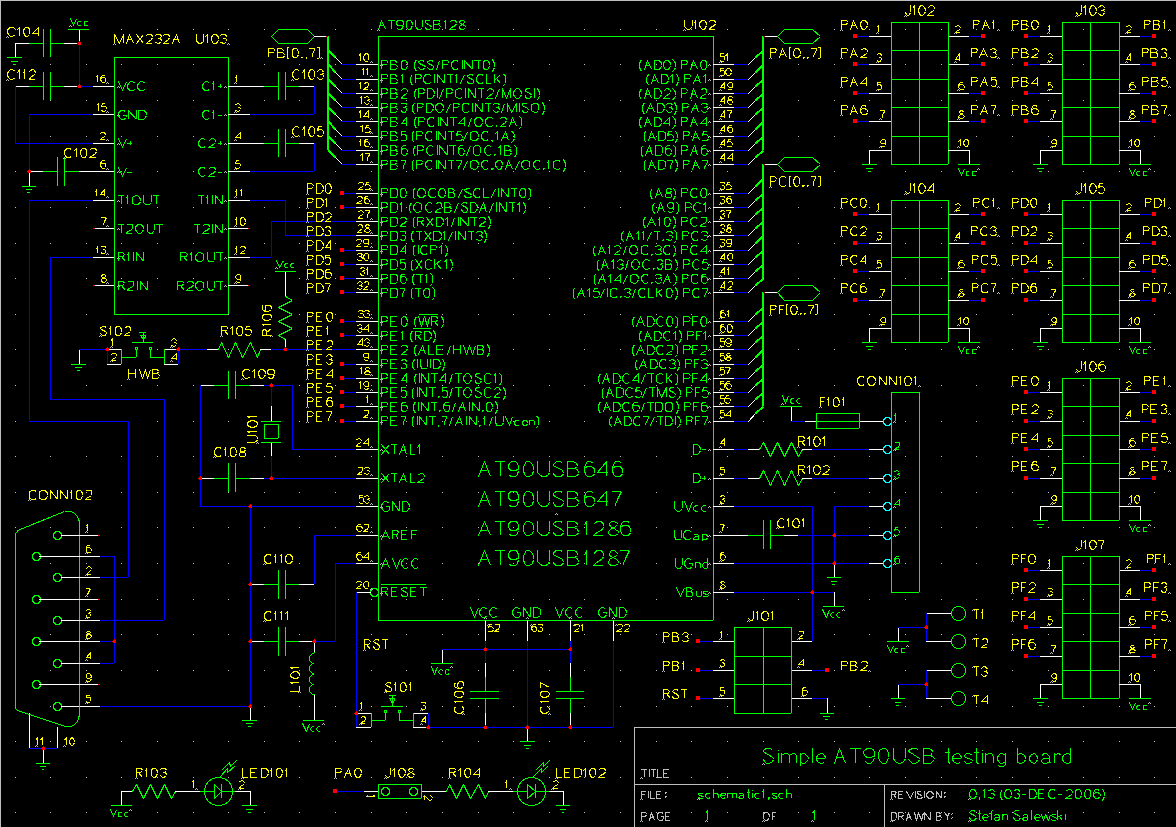
The circuit is supplied with electrical power by the USB. The programming of the AT90USB can take place by SPI (Serial-Programming-Interface, 6 pins) or by a USB-Bootloader. A Serial port realized with a MAX232A facilitates Debugging. Since the AT90USB is provided with a USB-Bootloader by its manufacturer, firmware can be uploaded directly over the USB interface. For this process the software "FLIP" available from Atmel is necessary (initially available for Windows only, now also for Linux), or with Linux the free program dfu-programmer of Weston Schmidt can be used.
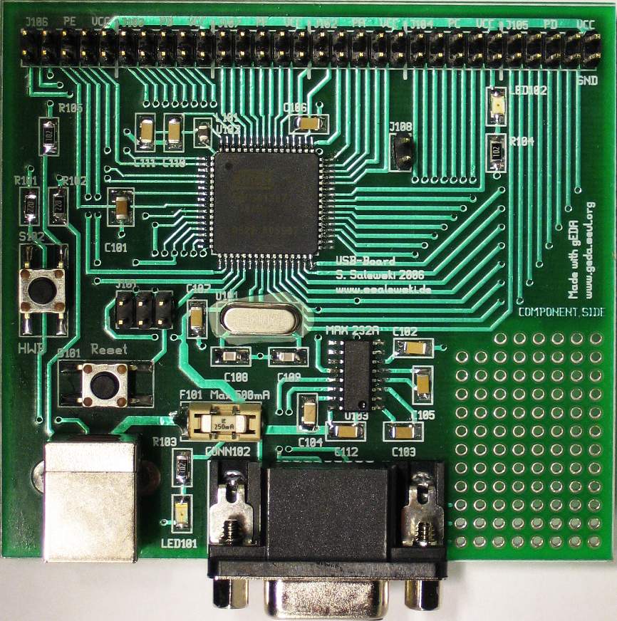
The board
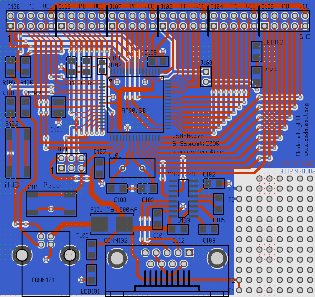
The layout of the printed circuit board and the schematics diagram was produced with the free gEDA-Software (gschem, gsch2pcb and pcb) on a PC running GNU/Linux (Gentoo AMD64). The AT90USB is available in 64-pin TQFP and QFN case -- used was the TQFP case, which can be soldered by hand with suitable soldering tools and some exercise. The board was manufactured using the Gerber files at a printed circuit board manufacturer. Here is a photo of the complete (hand soldered) board:
Bill of materials
| Part | Value | Case | Supplier | Order-Nr. |
|---|---|---|---|---|
| U101 (Crystal) | 16 MHz | XTAL_HC-49U | Reichelt | 16-HC49U-S |
| U102 (Controller) | AT90USB1287 | TQFP64_14 | ER-Tronik | 8061010 |
| U103 (RS232) | MAX232A | SO16 | Reichelt | MAX 232 ACSE |
| LED101,LED102 | 1206 | Reichelt | SMD-LED 1206 | |
| C101 | 1 uF | 1206 | CSD | 115-12R001 |
| C102,...,107,110,...,112 | 100 nF | 1206 | Reichelt | X7R-G1206 100N |
| C108,C109 | 15 pF | 0805 | Reichelt | NPO-G0805 15P |
| R101,R102 | 22 Ohm | 1206 | Reichelt | SMD 1/4W 22 |
| R103,R104,R105 | 1 k | 1206 | Reichelt | SMD 1/4W 1,0K |
| R106 | 50 k | 1206 | Reichelt | SMD 1/4W 51K |
| L101 | 10 uH | 0805 | Reichelt | JCI 2012 10u |
| J101 | CON_HDR-254P-3C-2R-6N Molex_8624 | Reichelt | SL 2X40G 2,54 | |
| J102, ..., J107 | CON_HDR-254P-5C-2R-10N Molex_8624 | Reichelt | SL 2X40G 2,54 | |
| J108 | CON_HDR-254P-2C-1R-2N Mill-Max_800 | Reichelt | SL 2X40G 2,54 | |
| S101,S102 (Push button) | LSH1301 | Reichelt | Taster 9315 | |
| CONN101 (USB_B) | CON_USB_TYPEB _Keystone_924 | Reichelt | USB BW | |
| CONN102 (RS232) | CON_DSUB_9F_AMP_747844 | Reichelt | D-SUB BU 09EU | |
| F101 | 250 mA | FUSE__Littelfuse_154 | Reichelt | SMD-HASF 0,25A |
(Total costs of all parts are approx. 20 Euro per board; the manufacturing of the PCB from the Gerber files is approx. 60 Euro for four pieces.
At this point I should mention three more or less important things: The presented USB board works fine with USB cables of medium length (approx. 2 m). But I get many transmission errors when I am using a 5 m cable. A solution to this problem is to place a 1 uF ceramic capacitor between USB power (VBus) and ground somewhere on the PCB board. (I have put this capacitor on top of the connector row of my board. You may substitute one of the existing 100 nF capacitors connected to VBus with one with more capacitance, but of course the better solution is to create an additional component on the PCB.) Initially I forgot to connect a pullup resistor to Pin E2 (HWB). Without this it occurred that the bootloader became active during reset unintentionally. This is fixed in the schematics and PCB, but that pullup is not visible on the photo of the board. The other point is, that USB specification suggest not to connect the case of the USB socket of a device to PCB ground. So for a redesign of the board we should cut this connection and replace it with a soldering bridge or a (unmounted) zero ohm resistor.
Using the following link you can download the schematics and board layout in gEDA format including a few of my schematic symbols and footprints as a compressed Tar-archive. Additionally the schematics are available as PostScript- and PDF-Documents -- in case that someone has no working gEDA suite installed but wants to print out the schematics.
- AVR_USB_gEDA-20061203.tar.gz ( 38K)
- AT90USB_sch.ps.gz ( 16K)
- AT90USB_sch.pdf ( 19K)
In order to be able to work with the gEDA files, additional to a properly installed gEDA suite the Footprint library of John Luciani is necessary. The schematic symbol of the AT90USB1287 is available (in revised shape) at www.gedasymbols.org together with many other symbols and footprints.
At the end some useful links:- www.atmel.com (AT90USB)
- www.gpleda.org (gEDA homepage)
- www.gedasymbols.org (gEDA schematic symbols)
- www.luciani.org/geda/pcb/pcb-footprint-list.html (Footprint library of John Luciani)
- www.reichelt.de (Parts)
- www.er-tronik.de (AT90USB)
- www.csd-electronics.de (Parts)
- www.bilex-lp.com (PCB manufacturer)